A copy of the article is available below:
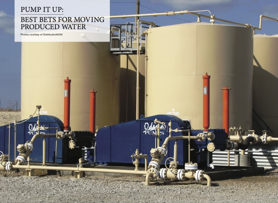
PUMP IT UP: BEST BETS FOR MOVING PRODUCED WATER
New trends have emerged in the world of water management for domestic oil and gas production as more companies look for ways to recycle produced water in lieu of injection into salt water disposal (SWD) wells.
For recycling to make economic sense, a consumer of treated produced water is needed. Typically, recycled water is used by companies conducting fractionation and completions, hence creation of demand for recycled water. Unfortunately, high volumes of produced water outpace the demand for recycled water and as a result, there is a tremendous surplus of produced water that is not recycled.
Looking at the Permian Basin water situation, we see there are an estimated 500 MMbbl of water produced monthly, while demand for completions is only about 200 MMbbl of water per month. As a result, the demand for produced water disposal is not going away any time soon as long as the surplus of non-recycled water remains.
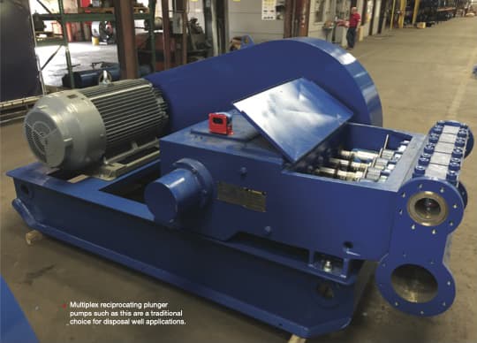
Recip-Pumps
Multiplex Reciprocating Plunger Pump: This design is a positive displacement pump that transfers liquid via plungers that reciprocate back and forth on a crankshaft. Internal spring-loaded valves function much like those in the human heart to prevent backflow.
Fluid volume transferred through the pump is directly proportional to revolutions per minute of the pump shaft. Most of the installed equipment base found in older oil and gas plays have recip-pumps installed on SWD applications. The reciprocating plunger pump design has been the standard in most oilfields for the past 50 years or longer. These pumps are configured with packing as a sealing method, which can result in some produced water leakage during operation. This leakage can be managed by the operator to limit negative environmental impacts.

H-pump
Centrifugal Horizontal Multistage Pump: This pump design employs multiple stages of impellers rotating on a common shaft to move the fluid. Multiple stage pumps like the H-pump generate the higher pressure needed to overcome the well’s backpressure.
Produced in a variety of sizes, these pumps can move larger volumes of liquid at various pressures. H-pumps are designed to handle much higher volumes of liquid than reciprocating plunger pump designs. In general, recip-pumps do not exceed about 20,000 BWPD while some H-pump designs can move 50,000 BWPD with a single pump. The centrifugal H-pump design incorporates a mechanical seal on the shaft that results in near zero leakage of liquid to the atmospheric side of the pump.
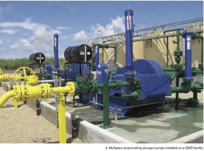
Reciprocating plunger pumps are most commonly found in SWD service in the Permian and other plays in southern states. The traditional flow requirements, ease of maintenance, high efficiency and lower initial cost have made recip-pumps the preferred design for many years. This is especially true for those SWD sites that typically move less than 10,000 BWPD. To meet the horsepower requirements found in traditional SWD service, the recip-pump pump design typically requires 480-volt power at the site which is generally in line with the power requirements of other equipment onsite.
Another type of centrifugal pump is often found in enhanced oil recovery (EOR) service. This pump design is known as American Petroleum Institute (API) 610 BB3. API 610 is the designation for the Oil & Gas Centrifugal Pump Standard for process applications.
API 610 BB3 pumps include a between-bearing multi-stage design and can handle much higher flow rates than the H-pump design. When in EOR service, API 610 BB3 pumps often require 3,000 horsepower motors and as a result, are found only rarely in SWD service. Pump applications for enhanced oil recovery water injection are a different topic than those used for disposal and may be discussed in the future.
Volume Trend
Salt water disposal wells have operated in the Permian for decades and their parameters, such as geological formation and historical dynamics, are understood. Traditionally, a disposal well in the Permian or Eagle Ford would see an average flow rate of 10,000 BWPD. More recently, operators are specifying single pumps to move 12,500 BWPD at pressures as high as 3,000 psi, which requires a centrifugal multistage H-pump design.
The trend toward pumping greater fluid volumes into Permian SWD wells is expected to continue. In some areas of the Permian, oil wells produce about 5 bbl of water for every 1 bbl of oil. Recent government figures show the Permian basin producing 3.5 MM b/d of oil, resulting in more than 17 MM BWPD to be recycled or disposed of. These recent production figures show Permian oil production has increased by more than 20 percent in just the past year.
Newly constructed disposal infrastructure and the required permitting has not has not come close to keeping up with the demand for increased water disposal. Even if we consider the increase in water recycling volumes, produced water takeaway capacity in the Permian has not kept up with demand.
As a result of this supply/demand imbalance, producers and their water management partners often try to move higher volumes of produced water down existing, and often nearly saturated, SWD wells. Instead of top flow rates and pressure specifications being 12,500 BPD with a maximum 3,000 psi, in the past year some operators have requested pumps capable of moving 20,000 BWPD at 4,000 psi.
As operators sought to process even greater volumes with increased flow and pressure requirements, requests for ever larger SWD injection pumps have been reported.
More Power
This push for higher flow rates and pressures from SWD well pumps is starting to exceed the capabilities of the traditional pump designs. Pump suppliers report more and more conversations with operators about putting three or more pumps in parallel to achieve the flow rates their customers are seeking.
In the past, a 12,500 BWPD flow at 3,000 psi could be achieved with a single H-pump and an ANSI 300 psi charge pump, piped in series. For this application, a motor of less than or equal to 800 hp could power a pump moving 1.10 specific gravity water and stay within the 480-volt power source requirements. It is understood that 800 hp motors can operate on 480-volt power provided the pump motor is used in conjunction with a variable-frequency drive or a soft-start in order to limit the in-rush current upon start up.
When the motor horsepower requirement is greater 800 hp, an increase in source voltage is required; medium voltage power (2,300 volt – 4,160 volt) is recommended. However, when a project requires migration to 4,160-volt pumping systems, the project economics change dramatically. In our experience, going from a typical 800 hp, 480-volt pump to a 900 hp, 4,160-volt pump and VFD package can more than double the price of a package.
Upgrading the disposal wellsite power system to manage a higher voltage pump can add a hefty chunk to the site CAPEX budget. When an operator seeks to increase capacity with pump systems that exceed the 800 hp motor threshold, it is recommended a new well be drilled or that multiple 480- volt pumps be configured in parallel in order to meet the desired flow rate. For example, four 12,500 BWPD, 480-volt pumps are capable of moving 50,000 BWPD when configured in parallel. Keep in mind that higher flow rates require higher pressures and that well pressure specifications must be considered as a function of the injection flow rate.
Effects of Water Density
Flow rate and pressure play equal roles when calculating horsepower requirements for an H-pump. The relative density, also known as specific gravity, of produced water has a linear relationship to the pump horsepower calculation. The higher the specific gravity of the water, the higher the motor horsepower required. Pressure on the discharge side of a centrifugal pump is also a function of the specific gravity of the liquid.
Water specific gravity is critical to proper pump and motor selection. In our experience, we have seen water specific gravity on SWD projects ranging from 1.03 to 1.20 depending on the region. It is recommended operators provide accurate water specific gravity data when submitting a project proposal request. Keep in mind that freshwater has a specific gravity of 1.00 at 70°F and a mass of 62.4 lbs/ft3 so, for example, produced water with a 1.12 specific gravity, has a mass of 69.9 lbs/ft3.
Pump suppliers will accept either form of the variable when specifying a system but providing an accurate account of this information is critical.
It is highly recommended disposal well operators work with an experienced pump package provider at the initial stages of disposal well design, if possible, in order to stay within the 800 hp, 480-volt power threshold. In our experience, this approach can save the operator millions in additional capital costs.
Time is Money
ith the rapid growth in oil development in places like the Permian, pump suppliers and manufacturers are competing heavily for a share of the SWD pump market. From a pump supplier’s perspective, the disposal well pump market is one of the most competitive sectors of the oil & gas marketplace.
From the oil & gas producer’s side of the fence, capital outlays for disposal well pumps do not typically generate a profit unless the producer has a play on a commercial SWD site.
The operator of a commercial salt water disposal facility takes in produced water, disposes of it for a fee and expects to turn a profit on the transaction. For producer-operated disposal wells, SWD pumps are often purchased from a supplier with the lowest price because for the producer, water adds limited value to the bottom line.
Lead times on disposal well pumps can vary from immediate in-stock delivery to as long as 16 weeks depending on the manufacturer, pump type, size and power requirements. If a producer seeks to start moving produced water as soon as the well starts producing oil, lead time is often the deciding factor in choosing a pump supplier.
We have seen this scenario play out quite often since produced water volumes are often unknown until the well starts producing oil. As Benjamin Franklin said, “time is money” and in these cases, the pump supplier with the quickest delivery usually wins the order.
DNOW, like other successful pump suppliers, sees the value in speed to market. Our investment in an extensive inventory of multiplex reciprocating plunger pumps and centrifugal H-pumps helps us to well serve the SWD market. Our inventory includes pumps for the 2,000 to 18,000 BWPD flow ranges with pressure coverages up to the 800 hp, 480-volt power limits. Our program for pump stock may not always offer the lowest price in the market, but we can often meet lead times for those seeking equipment in less than 2 weeks.
For water pump manufacturers and distributors, growth opportunities are not only found on the disposal side of the business. More producers and water management service providers are treating produced water for reuse than ever before. This leads to stronger demand for pumps within that sector. The pumps required to move produced water from a production site through a pipeline to a water recycle facility are similar to the pumps used for disposal. Although pressures may not be as high as the on water-disposal side, the same multiplex-recip and centrifugal H-pump designs can be configured for lower pressures.
Ready for the Cold
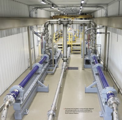
Cold weather environments such as the Bakken play in North Dakota bring additional challenges to the operator. Completely enclosed, turnkey pump packages for disposal facilities in these colder environments are common with operators there.
To serve this market, a number of pump suppliers, including DNOW, offer a bundled, fully equipped pump facility in an enclosed, insulated package. These plug-and-play packages can usually be hooked up quickly with less on-site construction time needed. However, it should be noted that these complete packages usually require more extensive lead times, often as long as 16-18 weeks. Operators should work with their suppliers to proactively plan the project’s requirements.
Another important application for oilfield water pump designs include those used for wellsite transfer and truck loading.
Local Transfer
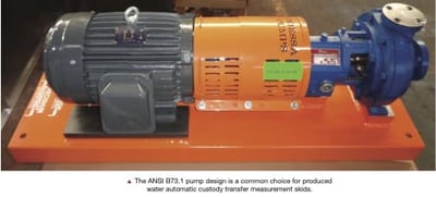
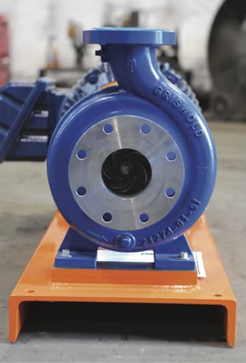
Oilfield operations require produced water to be transferred several times before it arrives at a recycle facility or disposal well. In some cases, produced water is pipelined from a production tank battery for many miles across land to a disposal well. In other instances, water may be loaded onto a truck at the tank battery for transport to the SWD or recycle facility. Either way, it is likely that for these water applications the pump used was the ANSI B73.1 pump design. Such compact pump designs are ideal for truck loading or for local transfer into a water gathering system. This pump design is also common on automatic custody transfer measurement skids as well.
As with the larger horsepower SWD injection H-pumps discussed above, ANSI B73.1 design pumps are constructed using Type 316 stainless steel (ASTM# A744 CF-8M). Classified as an austenitic stainless steel, Type 316 materials are designed to withstand contact with corrosive water and potential hydrogen sulfide (H2S) in produced water.
Corrosion Resistance
Likewise, pump mechanical seals should be manufactured with O-ring materials that withstand potential H2 S contact with the fluid. O-rings made with a synthetic rubber and fluoropolymer elastomer such as Viton® should be avoided in produced water transfer applications where H2 S may be present. O-rings manufactured with Aflas® or other similar materials are much better suited for corrosive produced water applications.
Most manufacturers of pump and mechanical seals understand the appropriate metallic and elastomer materials to install on produced water pumps as long as the operator provides accurate information on the pump application. It is highly recommended the operator inform the pump supplier of how the pump will be used and the expected H2 S content of the water, if it is known. Pump distributors and suppliers generally maintain stocks of ANSI pumps and should be able to respond in less than two weeks for most common ANSI pump sizes in Type 316 stainless steel material. Distributor delivery is often much quicker than a direct buy from the pump manufacturer.
In a commodity driven market like the oil and gas industry, forecasting where the pump market is heading in terms of recycle or disposal is complicated. What is known is that pumps will be needed to move fluids on either side of this business. By planning proactively and partnering with a reliable, knowledgeable pump supplier, getting the right pump for the right application helps assure consistent operations for the long term.
About the Author
Brian Verdehem is Director of Engineered Pumps for DNOW. He graduated from The Rochester Institute of Technology (RIT) in Rochester, NY, with a Bachelor of Science degree in Mechanical Engineering and has more than 25 years of experience in engineered industrial pumps and controls. His experience includes engineered pump applications in petroleum refining, petrochemical process, oil and gas upstream and midstream, LNG, power generation, pulp and paper, water treatment, food and beverage, and general industry. Mr. Verdehem co-authored a U.S. Patent and has written numerous technical articles on industrial pumps, applications and reliability. He conducts several presentations and training sessions annually on a wide range of subjects involving engineered pumps and controls.

About Odessa Pumps
Odessa Pumps, a DNOW company, has been a leader in providing solutions, packages, parts, repair, and machining for more than 37 years. Ranging from the pump needs of oil & gas fields to keep the water flowing for the cities and towns we call home, Odessa Pumps is your full-service pump company.
Learn more by visiting the Odessa Pumps website
Source version from Shale Play Water Magazine
This article is provided courtesy of Shale Play Water Management, a national magazine covering fluid-handling applications and solutions in the North American oil & gas industry.
The Shale Play Water Management magazine and website cover "real world" fluid-handling applications and solutions. They focus on the entire water cycle, and combine to be the number-one industry resource for important news, applications and technologies in the water-management sector.
The magazine's goal is for every issue to deliver the critical information that provides operators and those allied to the field with the information that is needed to do their job better and more efficiently.
For more information, please visit the official website: https://www.shaleplaywatermanagement.com/